Oh these doors! They are not really hard in any way, there are just a lot of steps and undoing what you did and then adjusting and re-doing it again.
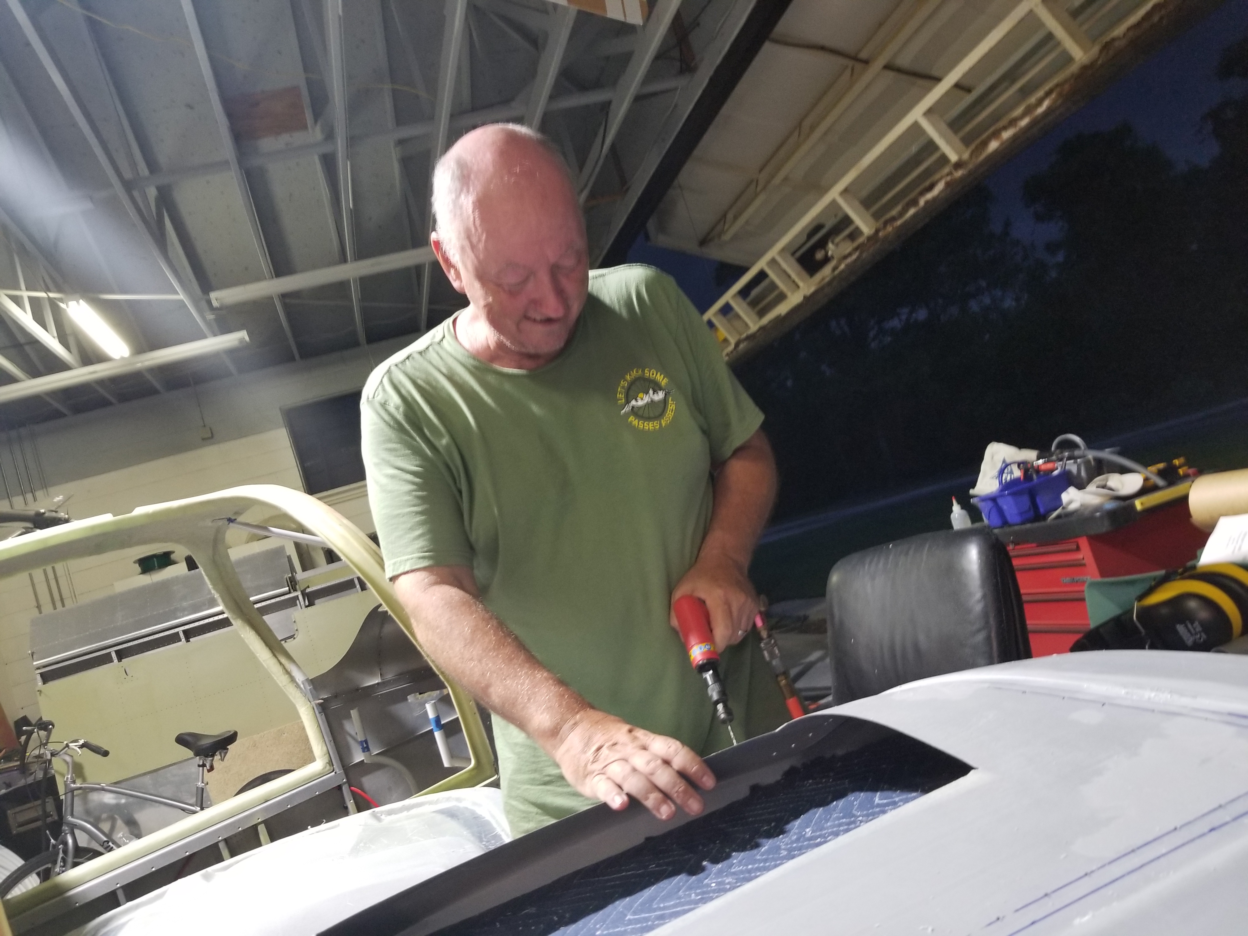
12/3/2020 Finding the perfect GAP for the door seal
I am using the McMaster door seal with the attatch flange width of .25 and the bulb diameter of 3/8. The part is :1120A411 Water- & Weather-Rst Rubber Push-on Seal with Bulb on Side, Hollow, for 1/4″ Edge, 3/8″ High, 50 ft. Length.
I wish I had this tool (below)before I started the gap, but when I was back in my NJ home getting it ready for sale, I came upon this tool and had a light bulb moment. This would be perfect for gapping the doors.
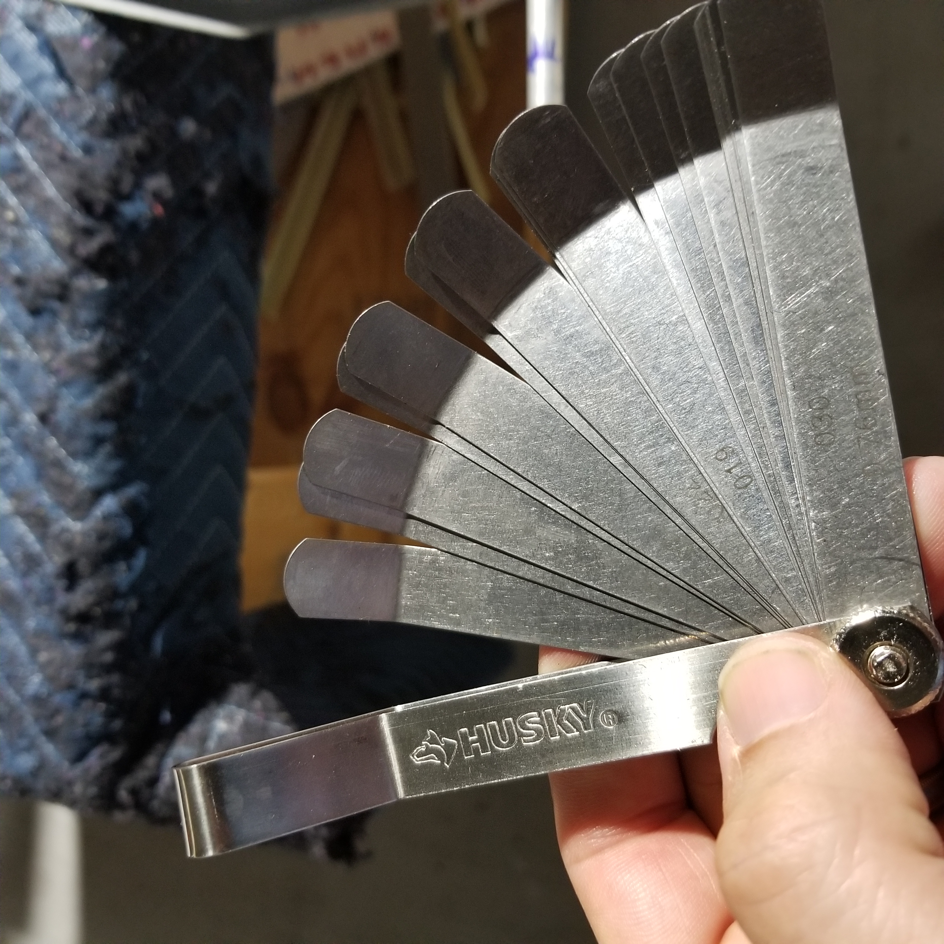
Using this tool, I measured the gap on my door that seemed to be perfect for compression of the bulb. I found it to be 0.300 of a Gap. Now I may remove my seal and adjust all the gaps using this tool for a uniform “squish”
12/18/2020 New Access panels in Upper Forward Fuselage
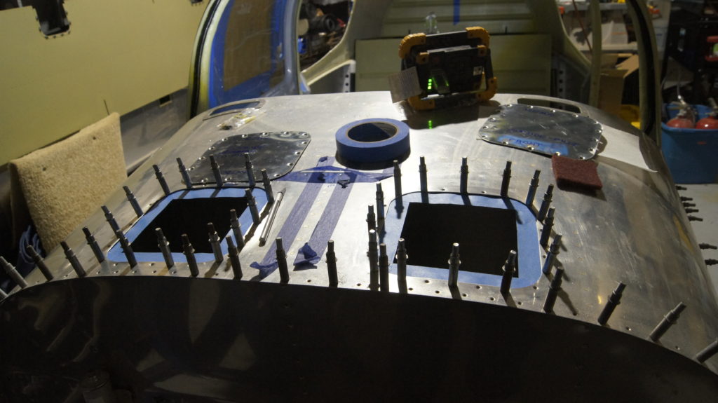
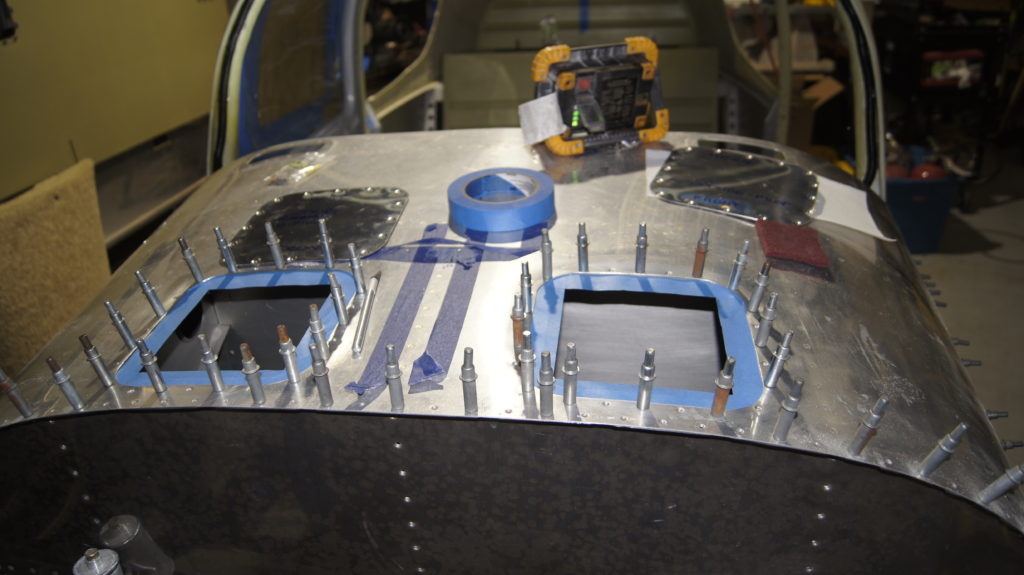
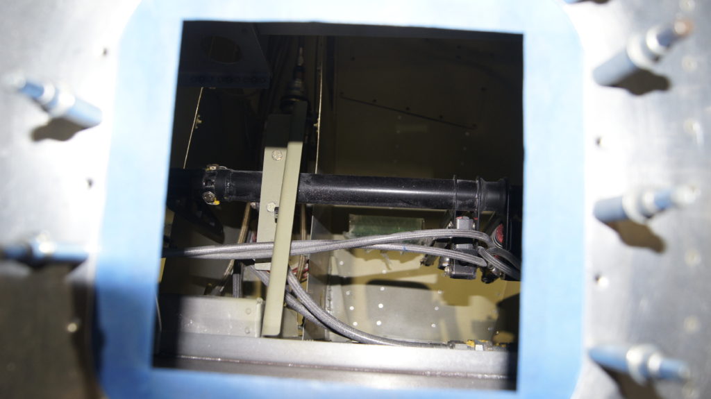
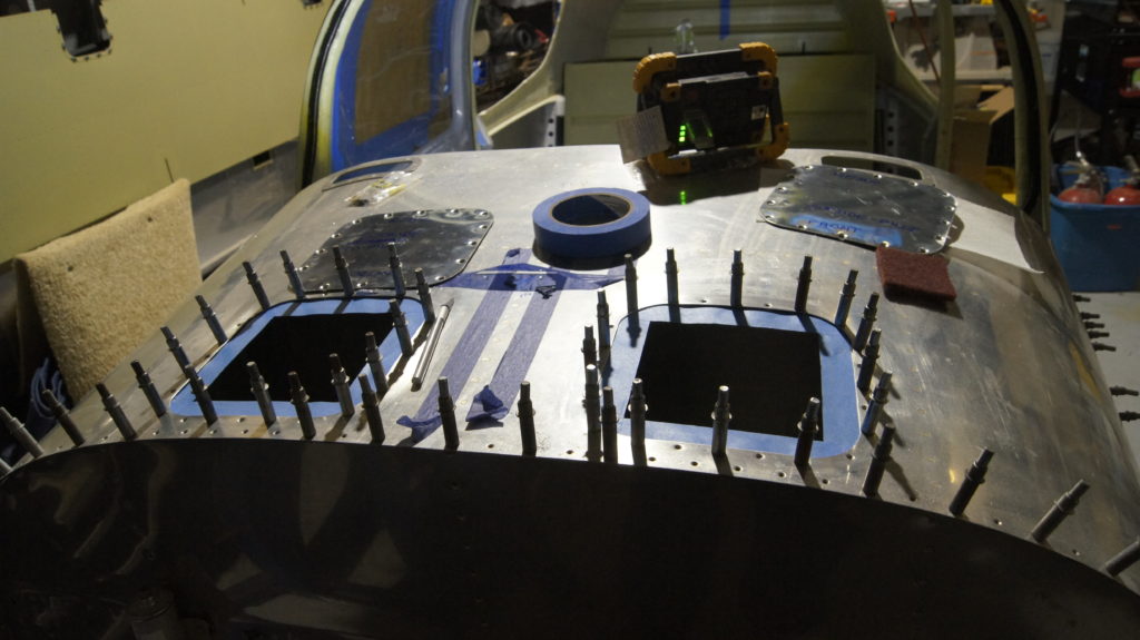
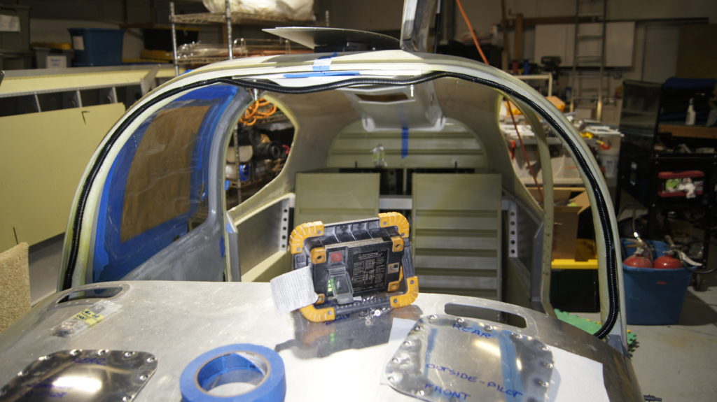
Vans recently came out (new to me anyway) access pannels for many models that can be placed forward of the fudelag panel and allow better access behind the panel. For the RV-10, these actually provide great access to the space behind he sub panel. I decided to install these and when cut out the first opening, was amazed at the benefit this will be to mount and access equipment to an area I would probably would never have mounted anything in.
Ove the last fer days I have cut the openings, matched drilled the rivet holes for the reinforcing plate. alodined them, riveting countersunk #8 nut plates to them and I am now ready to rivet them on. I needed to buy some fresh proseal to seal them against the weather.
12-23-2020 Mounting the Overhead Console
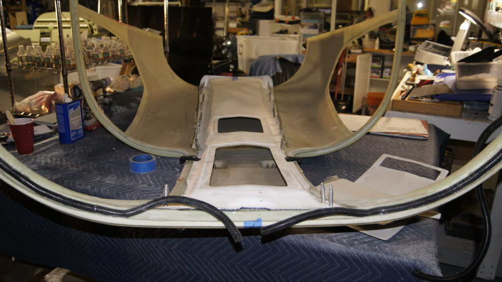
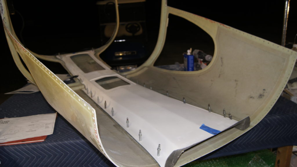
Last night I removed all the fasteners that were holding the canopy in place. It was time to take this off for the last time and prep it for the installation of the overhead console and for any finishing.
This morning, Carol helped me remove it, flip it over and place it on the table. Now that I had a good look at how it was fitting, I decided to trim some parts that were preventing it from completely sitting down on the canopy. My trimming worked for many spots, there there will still be a good amount of filling and sanding to smooth it out.
Once I thought I had it good, I removed the clekos and separated it from the canopy. I sanded down the mating surfaces with#80 sandpaper, blew the dust away and used some acetone to clean it up and ready it for epoxy.
IO mixed some West System Epoxy using the slow hardener. I used a total of 6 quirts and then added cotton FLOX to thicken it up. I put a bead down all the flange locations o the canopy. I then mixed an additional batch of epoxy (2 squirts) into a cup and used a brush to wet down the overhead console flanges, much like buttering a tile.
I carefully placed the overhead console in location, found the cleko holes and fastened it to the canopy. I then cleaned up any epoxy. I will let this stand at least overnight.
Next up is the switch pod mold.
12-26-2020 Continue with overhead console and finish rudder cable hookup
The canopy was attached. I started sanding the lip of the overhead console and feathering it into the canopy and realised the hard epoxy was going to be tough to sand. I decided to instead fill the valley of the where the canopy meets the lip of the overhead console with a very thick mix of epoxy and glass bubbles. I made the epoxy mix the consistency of frosting. I know this is easily sandable. With it being really cold here in Florida, the epoxy will take a long time to cure.
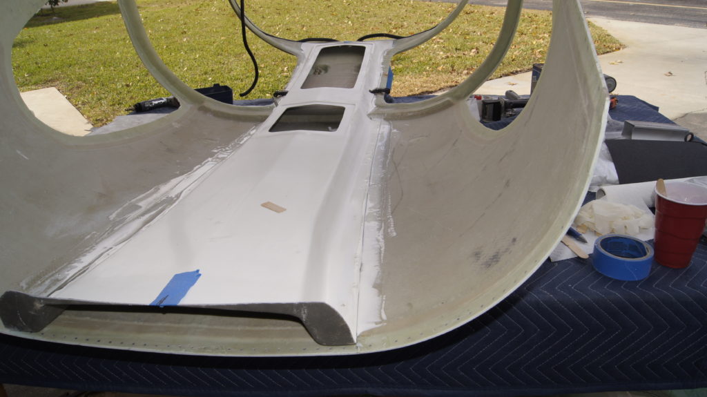
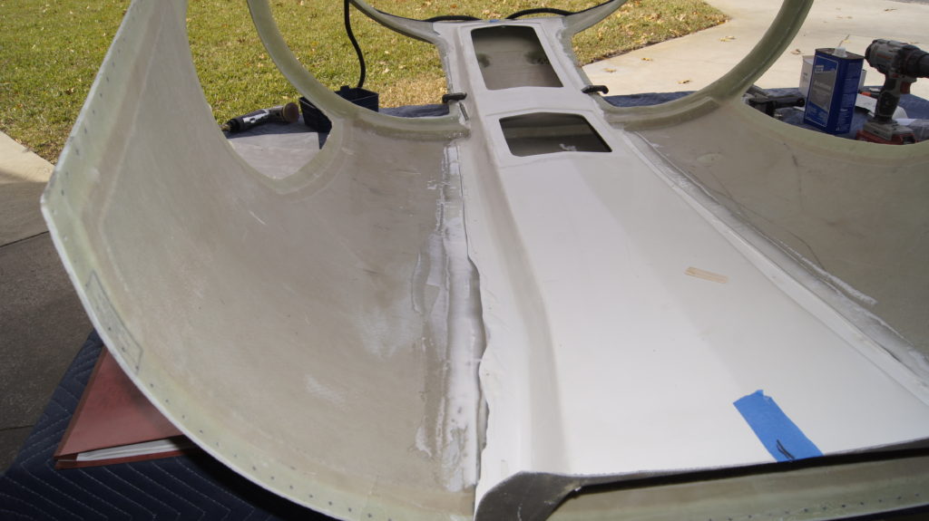
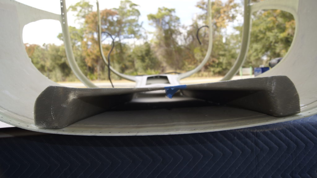
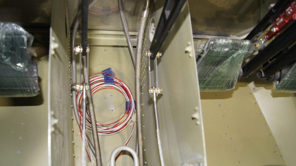
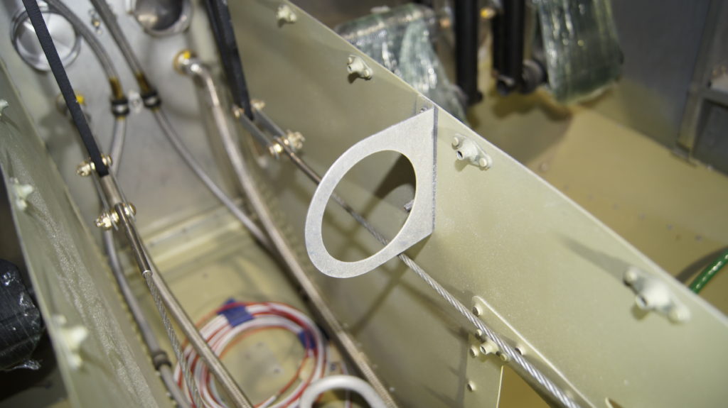
While waiting for the epoxy to cure, which is did not until late in the evening, I decided to finish the rudder cable connections. I had not finsihed the connections when doing the fuselage because I needed longer clevis pins/screws due to the width of the Control Approach rudder pedal arm width. At first I inserted the screws/pins with the dead on the side closest to the tunnel placing the nut on the inside of the tunnel. I decided to revers this as the castle nut and cotter pin might abraid anything and they middle of the tunnel has the heating scat tube.
I also noticed that the rudder cable (right cable) was rubbing on the scat tubing bracket. This will need to be corrected. I have a few ideas and will address later.
1/13/2021 Overhead Switch Pod
I decided to purchase the Aerosport overhead switch pod rather than make my own. IT arrive this past Saturday and I have been figuring out how to mount it and where to mount it. I have an older Accuracy Avionics overhead console, so the Aerosport switch pod does not fit all that well.
I reviewed how the South Florida Sport Aviation overhead trim worked and realized I could mout this a bit forward of where it mounts on the Aersport overhead console and the leather tri will work well. It also moves the switch pod a2 inches foward making it easier to see when in the front seats.
The switch comes with 4 mount points. These were elevated from my overhead console (not making contact) so I needed to figure out how to fill the gap whiel still making the switch pod removeble. If it is not removeable, getting the center support bar on and off during the build will be almost impossible.
I also took the available time to mix up a small batch of Super-Fill. This is my first time using it. I used the small batch to fill in some areas on the canopy top to overhead console areas that may be visible when the headliner is in. The SuperFill (blue in the pictures) will set overnight and be sanded tomorrow.
April 7, 2021 Fuel line pressure testing
over the last 3 days I have decided to pressure teak the fule and brak lines prior to performing more work that would make accesign them more difficult. At first I put a cap on the firewall fitting on the supply line and then added a fitting with a schraeder valve at the wing root supply line. I turned down my line regulator to 10 PSI and applied pressure ot the line. Itpressurized but quicky leaked down to o in a few minutes. I did find a loose B nut at the fuel pre-filter fitting that I tightened. I then decided to perform this test in smaller segments.
I turned the fuel valve to the off position and then applied air pressure. Pressure rose to 15 PSI. I left pressure applied for the evening. The next afternoon at 2 PM the pressure was still at 15 PSI. Now we know that those segments up to an including the fuel valve are good. Next is to add the segement from the fuel valve to the pre-filter, fuel pump and to the firewall.
Later today, I removed pressure from the system. I turned the fuel valve to the left tank (no tank on yet) and pressurized the system again. This will pressure test the left fuel line from the wing root to the firewall. I pressurized it to 25 PSI and will keep it there until the morning. All these lines at conductive teflon with a braided Stainless Steel cover and swaged fittings. They test each line to something like 3,000 PSI. I am less worried about the lines and more worried about my ability to screw the fittings together tight enough.
Unfortunately, this leak test confirmed a leak somewhere between the fuel valve and the firewall. I too the opportunity to swap out the firewall bulkhead fittings which were straight thruou fittigns with the new 45 degree fittigns suggested by Aircraft Speacialty for the Fly EFII installation with thier hoses. Oncve the swap was completed, I pressurised the line to 25 PSI. Maybe it was this fitting? That would be nice.
April 7, 2021 Right side door trim
The right side door now needs to be trimmed so there is a gap around the outside and no interference. This door already fits better than the left side did before trimming. This side should be easy. sand away andy interference, add the door seal and we are mostly done. This should only take a few building sessions.
April 8, 2021
I checked the pressure readin after leaving it at 25PSI overnight. The pressure was down to 20 PSI. Not much of leake, but I think we want no leak. I looked over some fittings and tried to tighted them. I was abl to tighten a few a bit more. I then applied 32 PSI. The results are showing it is slowly going down. After an overnight it went from 32 PSI at the begining around 4 PM to 19 PSI at 8 AM on April 9th 2021. The volume is so small in the lines, that this could just be an expansion of th lines themselves.
Andair did get back to me and they said they test the fuel valve up to 80 PSI and as low as 3PSI. They can test to higher pressures but you need to send the valve back to them.
I have decided that a leake in the system is not something I want to experience early on in the final phases of the build. I will continue to pressure test the remaining lines. To add even more confidence, I will be buying Qty 2 5 gallon gas cans and getting 5 gallons of 100LL. I will fabricate two short tubes (one flop tube) to connect to the supply and return lines at the ring root. the other end will go into the 5 gallon gas cans. This setup allows me to:
- Run 100LL through the lines and clean them out
- Test each pump and run them for a period of time to check for function, current draw and infant mortality
- Test the fuel pressure regulator and set that pressure at 35 PS
- Check for fuel leaks with real fuel
April 17, 2021
This weekend was a very positive one. As described, I purchased the fuel containers and yesterday I purchased 5 gallons of 100LL. I made the two fuel pickup and return lines that attached to the wing root fitting and placed one in the full fuel container and the return line in the empty one. Using my variable voltage and current power supply, I applied 12 volts to Pump #1 (left side pump) and it started pumping fuel through the system and returning it to the empty container. No leaks Yes. I did this test several times and the results were the same every time.
5 gallon transferred in 6 minutes. Voltage was 12 volts and amps we 2.0 amps. This equates to a fuel flow of 50 gallons per Hour or GPH. I then tried this on pump #2 with identical results. No leaks in the fuel lines
I then decided to run both pumps at the same time, This would simulate a takeoff or landing or emergency configuration and I wa able to transfer the 5 gallons in 4 minutes or 75 GPH. The current draw did surprise me at being just under 5 amps (4.8 amps) which was more than both pumps together. I think this was due to the high pressure at the outlet of the pumps as they competed to push fuel through the same 3/8 line.
I know I need to add the fuel pressure regulator to this test but that will come in a few days.
With the left side plumbing looking good, I moved my air pressure testing to the right side of the plan. I readjusted (tightened) the indicator and the schrader valve and then attached them to the right side wing root fuel supply and return lines. I applied 35 PSI of air pressure and it held at 35 for a few hours and into the evening. I went to bed and woke up this AM and the pressure had gone down 1, mayby 2 PSI. Either way it was less than what I experienced on the left hand side. I feel very confident that there will be no leaks today when I do the fuel flow testing on the right side.
I should be able to perform the fuel testing on the right hand side today. I should also be able to add the fuel pressure regulator supplied by FlyEFII and perform the testing again on both sides. I would expect higher current and possibly lower fuel flow.
Next up after this is the same testing on the hydraulic lines. Then I can move on to the upper forward fuselage, windscreen, gear legs and engine hang.
April 20, 2021.
I tested the right side fuel lines under no pressure and achieved the same results as the left side.
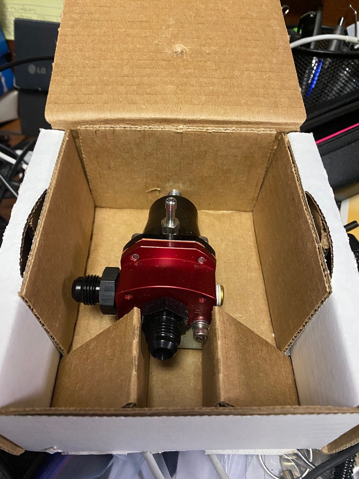
I then hooked up the fuel regulator to test under 35 PSI but I need a 1/8 NPTM to 1/4 NPTF fitting to connect to the pressure gauge. I will pick one up tomorrow
 .
.
April 21, 2021
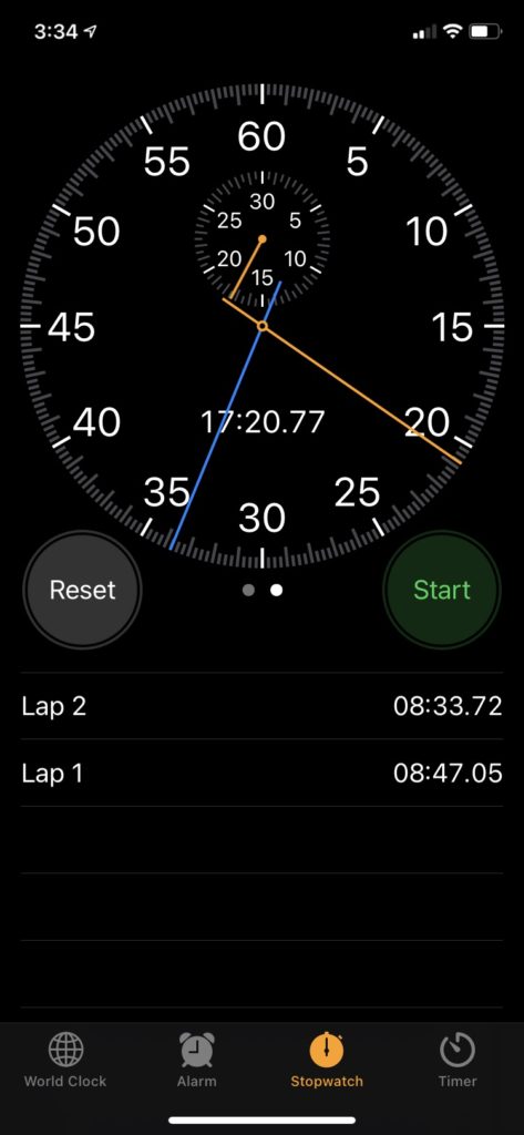
Pressure regulator connected up from the firewall fitting and then the return going through the firewall back to the wing root. Initial test on running 5 gallons through it while the regulator was set to 35 PSI was 8 minutes 47 seconds or .57 Gallons per minute or 34.29 and 35.29 gallons per hour (pump 1/Pump2). The stopwatch timing is shown below.
When I tried to perform this same test with the pressure regulator using both pumps active, the pumps could not produce any flow, I believe this was due to an inadequate power supply since the power supply displayed a very low voltage. The pumps tried to operate but probably drew more current than the supply could output. I tested both pumps individually again and they each worked as expected.
May 8 2021
Over the past few days I was able to get the latches working on both boors and install the engine mount. I am also starting to finish some smaller tasks that never completed. One of those smaller tasks was to mount the door strut with the proper bushings.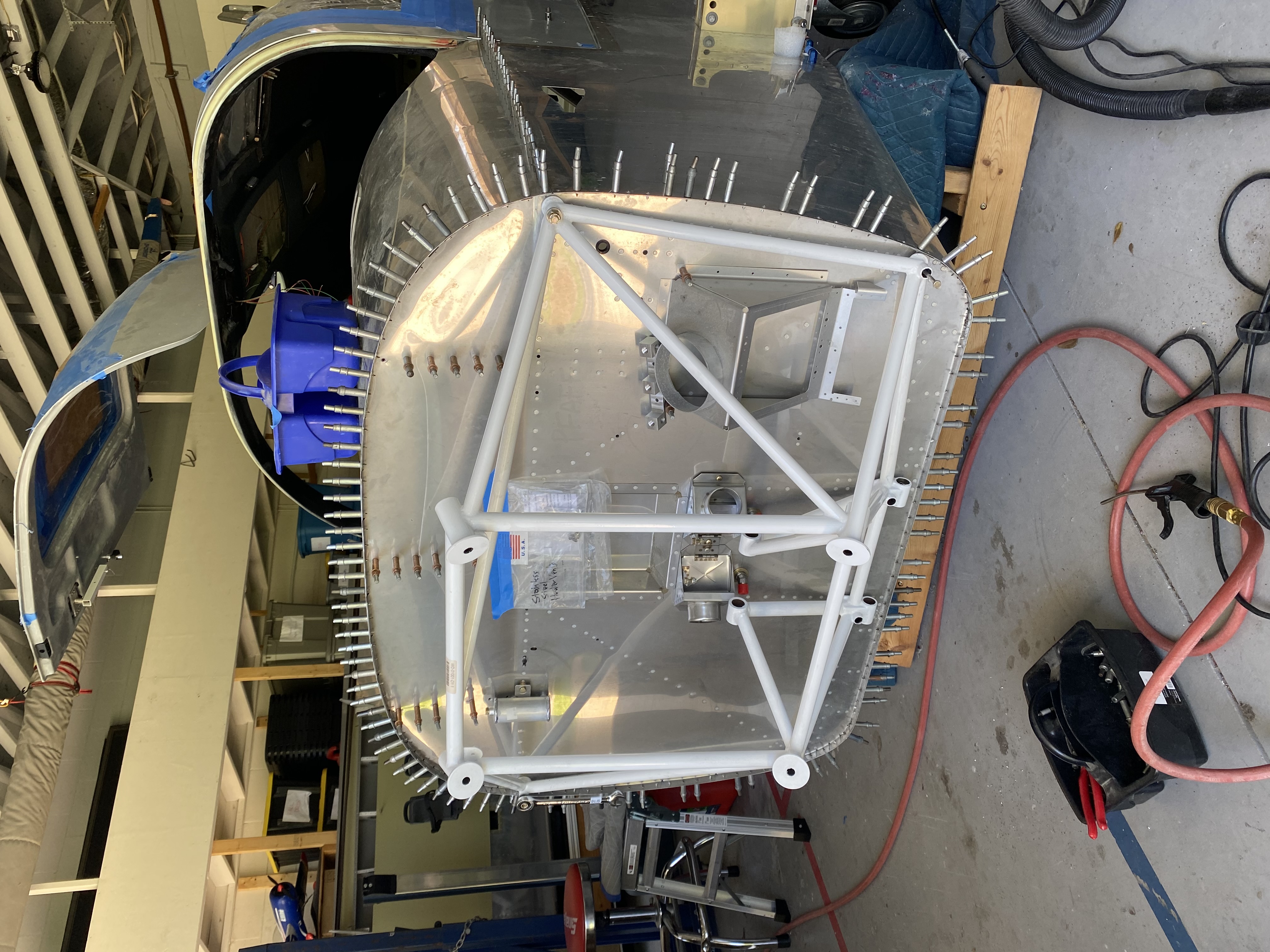
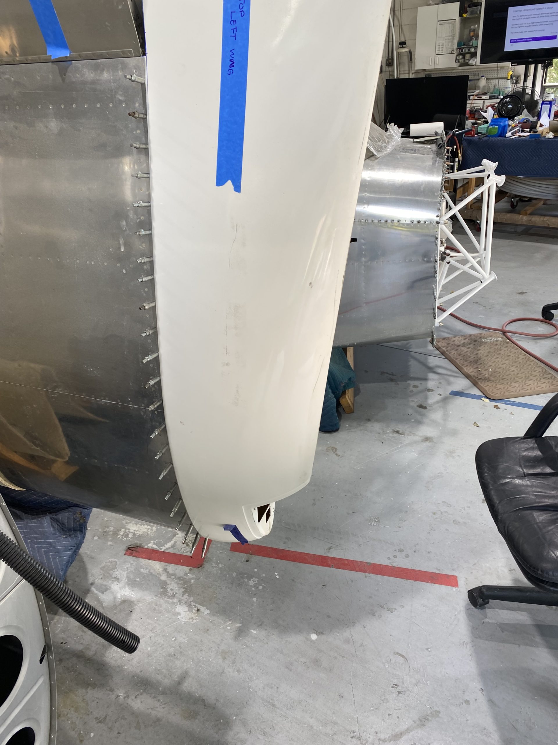
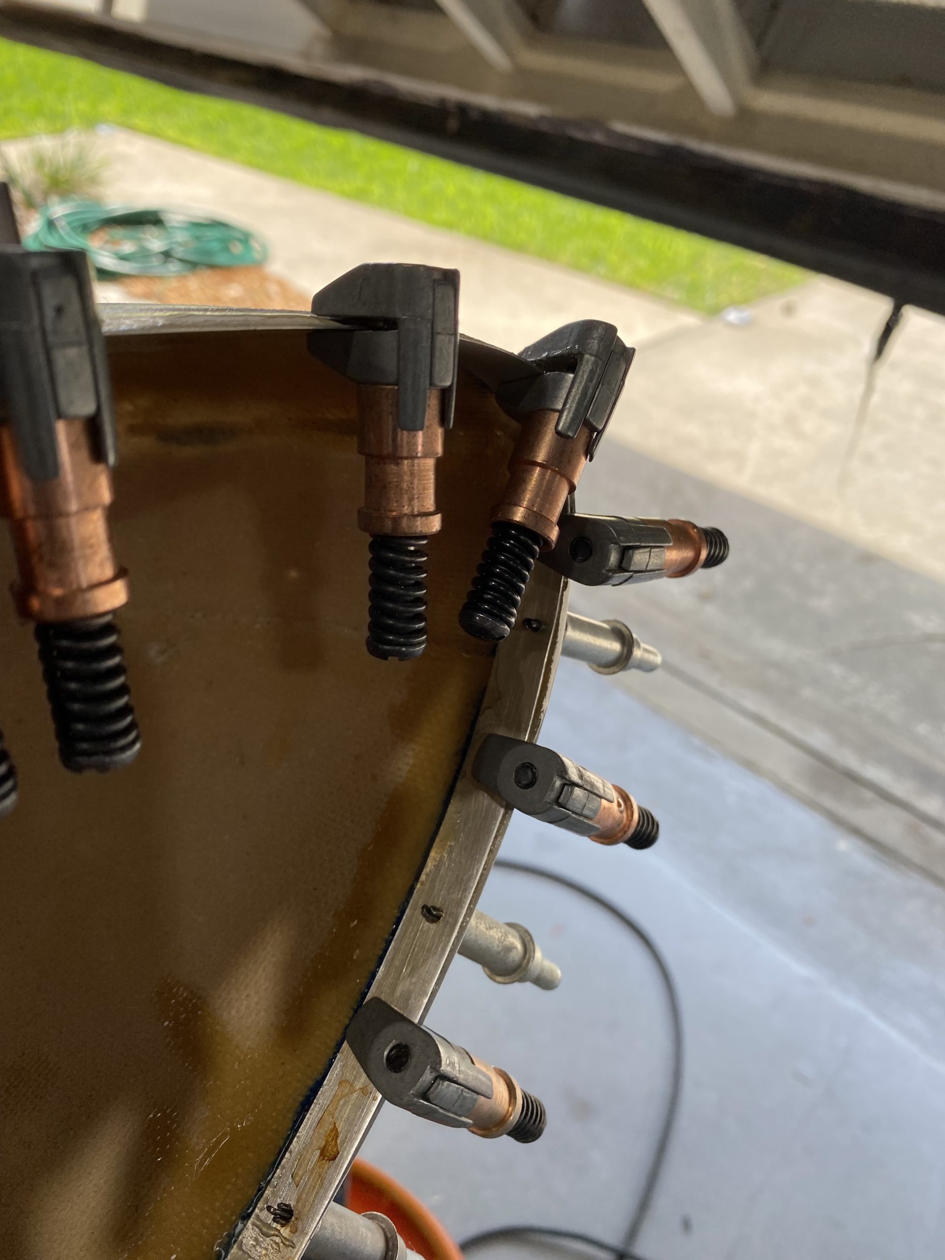
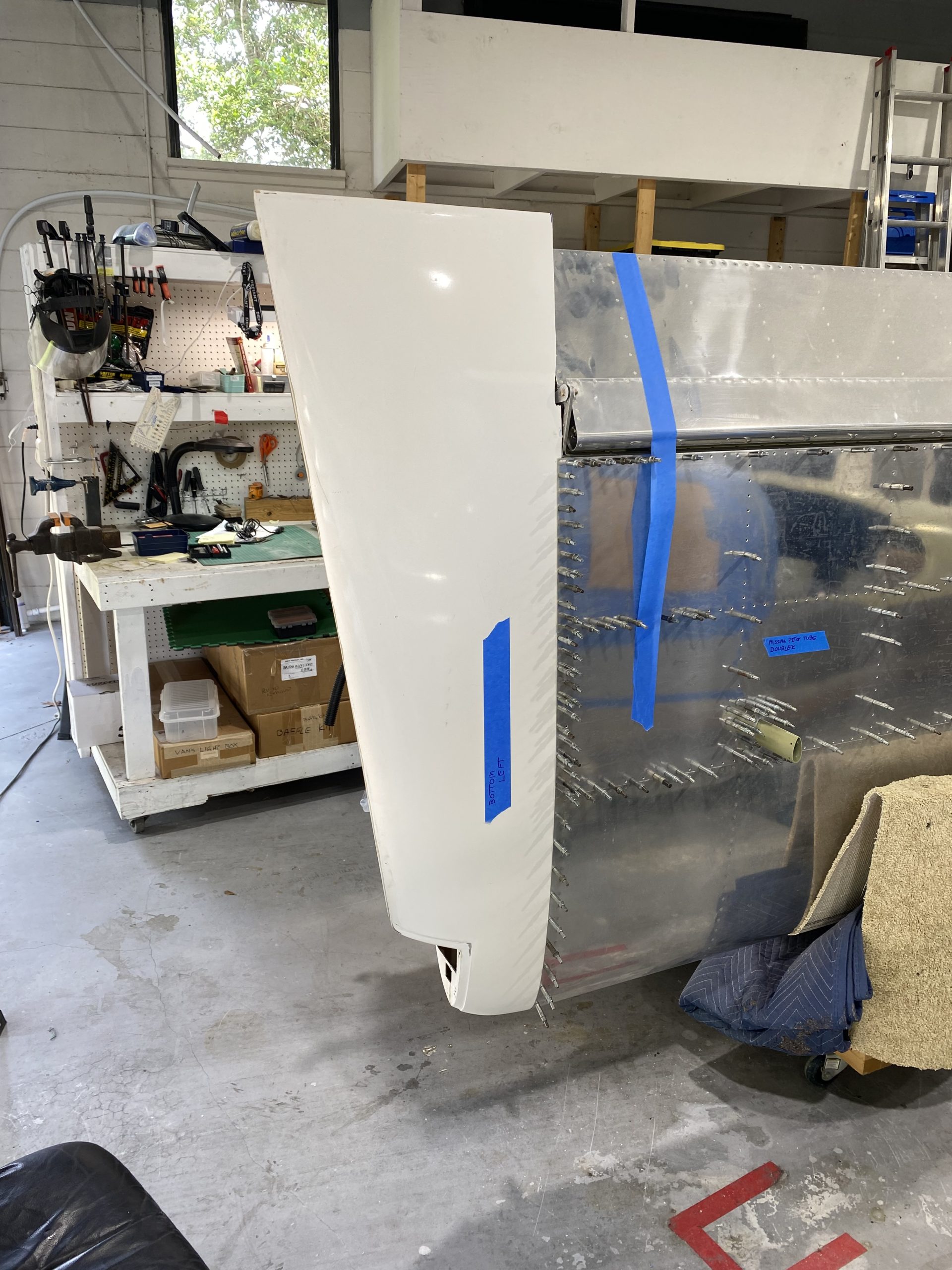
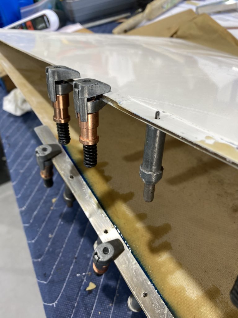
I continue to work on my power diagram and wiring schematic. While I those are being completed I am finishin up other smaller not-completed tasks. One taks is to attached the wing tips. What seems easy and simple always turns into a longer project. I will be using screws and nutplates. The nutplates get riveted on so I wanted to add a metal rivet backing strip to add strength. Vans has still not shipped the trips so I went and made some. I foirst had to trim the joggle to the right dimensions , fit the tip and them match drilled. Once drilled, I removed them and clamped the rivet backing strip in place and match drilled the backing strip. When doing this, I made sure the tip was in the same shape as it would be on the wing. The weight of the clecos and clamps had the tendency to collapse the tip edges together, which “may” impact the actual hole and shape when match drilling the backing strips to the tip.
Once drilled and clecoked, I dissassemled, cleaned and alodined the metal. I then reattached them using straight epoxy and let it cure to a thick but flexible state. In this state I mounted it back to the wing and clecoed it place so the tip and backing strip dry and harden in the final shap it needed to be.
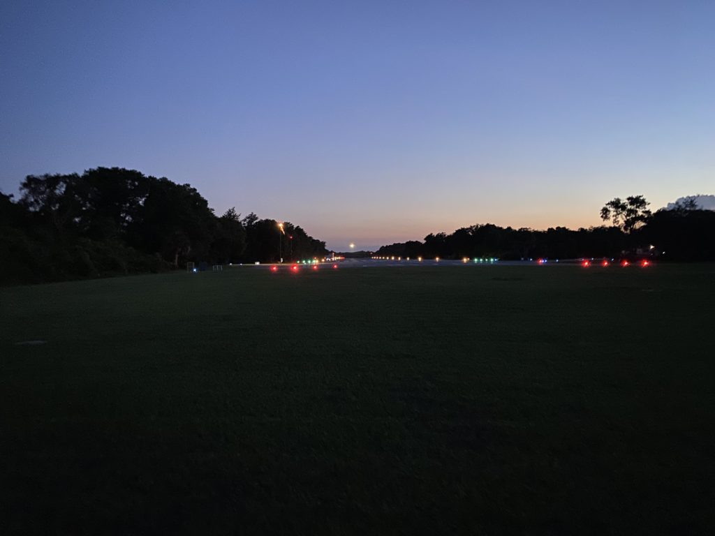
I took a walk a few nights ago and this was the view as I was close to home. Looking down runway 24 as plane was coming in to land.
June 20, 2021 Wing Tips
Today I challenged myself to finish my wing tips. I fell short by 3 floating nutplates. I am using floating nutplates because the floating threat allows the screws to line up and properly seat in the dimple. It is mich better that the fixd nutplates. I finali drilled the holes to #26 for a #6 100 degree countersunk screw and removed the tips from the wing. Using a nut plate jig, I drilled holes for the rivets. I deburred the metal rivet backing stips and them proceeded to countersing the #6 and #40 holes as appropriate. I finished around 9 PM with just 3 nutplates short.
I also acquired a new action cam and used it in time lapse mode to restart capturing my build